Radar Using Arduino & Ultrasonic Sensor
Project Fee:Negotiable
Project Discount:0
Project Duration:7 Days
How to Make a Radar Using Arduino & Ultrasonic Sensor.
Introduction:
In this project, I will show you how to design a simple
Radar Application using Arduino and Processing. This Arduino Radar Project is
implemented with the help of Processing Application. Radar is a long-range object detection system that uses
radio waves to establish certain parameters of an object like its range, speed
and position. Radar technology is used in aircrafts, missiles, marine, weather
predictions and automobiles.
Even though the title says Arduino Radar
Project, technically the project is based on Sonar technology as I will be
using an Ultrasonic Sensor to determine the presence of any object in a
particular range. The
Arduino Radar Project is more of a visual project than it is a circuit
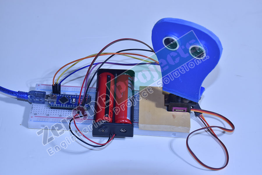
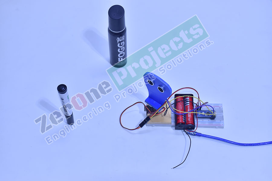
implementation. Of course, I will be using different hardware like Arduino Nano,
HC-SR04 Ultrasonic Sensor and a Servo Motor but the main aspect is the visual
representation in the Processing Application.
Circuit Diagram:
If you look at the circuit diagram, the design of the circuit for this project is very simple. The control pin of the servo is connected to Pin 12 of the Arduino while the TRIG and ECHO Pins of the Ultrasonic Sensor are connected to Pins 10 & 11 of Arduino respectively. A separate 5V power supply (with common GND) is given to the Servo Motor and the Ultrasonic Sensor.

Figure: Circuit Diagram of Radar Using Arduino & Ultrasonic Sensor.
Required Component:
·
Arduino
Nano
·
HC-SR04
Ultrasonic Sensor
·
TowerPro
SG90 Servo Motor
·
Mounting
Bracket for Ultrasonic Sensor (optional)
·
Connecting
Wires
·
Jumper
Cables
·
5V
Power Supply
·
USB
Cable (for Arduino)
Software
·
Arduino
IDE
· Processing Application


Radar Output :

Summary:
This project is truly interesting and
workable. By following the rules given to us, it will work for 100%. You can
make it for your own use as it has very high accuracy.
[N.B: If you have any problems working, please contact us and we will
assist you In-Sha-Allah. ]
//*****************************ZerOne BD Ltd*************************
//*********************ZerOne Projecs ******************
//*********************ZerOne Tech******************
//            Code Developed By...
//            Engr.Md.Nazmuzzaman Jomadder
//            ZerOne BD Ltd.
//            Contact: 01676998099
//            E-mail:sumonj.eee@gmail.com
//            Office:
//            ZerOne BD Ltd.
//            Plot#03(1st Floor),Road#04,Sec#6/ka.
//            Mirpur, Dhaka-1216
//            Contact:01676998099
//            E-mail:
//            projects.zeronebd@gmail.com
//            zeronebd16@gmail.com
//            bd.zeronetech@gmail.com
//            Web:
//            www.zeronebd.com
//            www.zeronetechbd.com
//            projects.zeronebd@gmail.com
//.................................................................
//***Arduino Code***
#include .
const int trigPin = 10;
const int echoPin = 11;
long duration;
int distance;
Servo myServo;
void setup() {
  pinMode(trigPin, OUTPUT);
  pinMode(echoPin, INPUT);
  Serial.begin(9600);
  myServo.attach(12);
}
void loop() {
  for(int i=15;i<=165;i++){
  myServo.write(i);
  delay(30);
  distance = calculateDistance();
  Serial.print(i);
  Serial.print(",");
  Serial.print(distance);
  Serial.print(".");
  }
  for(int i=165;i>15;i--){
  myServo.write(i);
  delay(30);
  distance = calculateDistance();
  Serial.print(i);
  Serial.print(",");
  Serial.print(distance);
  Serial.print(".");
  }
}
int calculateDistance(){
  digitalWrite(trigPin, LOW);
  delayMicroseconds(2);
  digitalWrite(trigPin, HIGH);
  delayMicroseconds(10);
  digitalWrite(trigPin, LOW);
  duration = pulseIn(echoPin, HIGH); time in microseconds
  distance= duration*0.034/2;
  return distance;
}
//***Processing Code***
import processing.serial.*;
import java.awt.event.KeyEvent; port
import java.io.IOException;
Serial myPort;
String angle="";
String distance="";
String data="";
String noObject;
float pixsDistance;
int iAngle, iDistance;
int index1=0;
int index2=0;
PFont orcFont;
void setup() {
 size (1200, 700); // ***CHANGE THIS TO YOUR SCREEN RESOLUTION***
 smooth();
 myPort = new Serial(this,"COM5", 9600); // starts the serial communication
 myPort.bufferUntil('.'); // reads the data from the serial port up to the character '.'. So actually it reads this: angle,distance.
}
void draw() {
  fill(98,245,31);
  // simulating motion blur and slow fade of the moving line
  noStroke();
  fill(0,4);
  rect(0, 0, width, height-height*0.065);
  fill(98,245,31); // green color
  // calls the functions for drawing the radar
  drawRadar();
  drawLine();
  drawObject();
  drawText();
}
void serialEvent (Serial myPort) { // starts reading data from the Serial Port
  // reads the data from the Serial Port up to the character '.' and puts it into the String variable "data".
  data = myPort.readStringUntil('.');
  data = data.substring(0,data.length()-1);
  index1 = data.indexOf(","); // find the character ',' and puts it into the variable "index1"
  angle= data.substring(0, index1); // read the data from position "0" to position of the variable index1 or thats the value of the angle the Arduino Board sent into the Serial Port
  distance= data.substring(index1+1, data.length()); // read the data from position "index1" to the end of the data pr thats the value of the distance
  // converts the String variables into Integer
  iAngle = int(angle);
  iDistance = int(distance);
}
void drawRadar() {
  pushMatrix();
  translate(width/2,height-height*0.074); // moves the starting coordinats to new location
  noFill();
  strokeWeight(2);
  stroke(98,245,31);
  // draws the arc lines
  arc(0,0,(width-width*0.0625),(width-width*0.0625),PI,TWO_PI);
  arc(0,0,(width-width*0.27),(width-width*0.27),PI,TWO_PI);
  arc(0,0,(width-width*0.479),(width-width*0.479),PI,TWO_PI);
  arc(0,0,(width-width*0.687),(width-width*0.687),PI,TWO_PI);
  // draws the angle lines
  line(-width/2,0,width/2,0);
  line(0,0,(-width/2)*cos(radians(30)),(-width/2)*sin(radians(30)));
  line(0,0,(-width/2)*cos(radians(60)),(-width/2)*sin(radians(60)));
  line(0,0,(-width/2)*cos(radians(90)),(-width/2)*sin(radians(90)));
  line(0,0,(-width/2)*cos(radians(120)),(-width/2)*sin(radians(120)));
  line(0,0,(-width/2)*cos(radians(150)),(-width/2)*sin(radians(150)));
  line((-width/2)*cos(radians(30)),0,width/2,0);
  popMatrix();
}
void drawObject() {
  pushMatrix();
  translate(width/2,height-height*0.074); // moves the starting coordinats to new location
  strokeWeight(9);
  stroke(255,10,10); // red color
  pixsDistance = iDistance*((height-height*0.1666)*0.025); // covers the distance from the sensor from cm to pixels
  // limiting the range to 40 cms
  if(iDistance<40){
    // draws the object according to the angle and the distance
  line(pixsDistance*cos(radians(iAngle)),-pixsDistance*sin(radians(iAngle)),(width-width*0.505)*cos(radians(iAngle)),-(width-width*0.505)*sin(radians(iAngle)));
  }
  popMatrix();
}
void drawLine() {
  pushMatrix();
  strokeWeight(9);
  stroke(30,250,60);
  translate(width/2,height-height*0.074); // moves the starting coordinats to new location
  line(0,0,(height-height*0.12)*cos(radians(iAngle)),-(height-height*0.12)*sin(radians(iAngle))); // draws the line according to the angle
  popMatrix();
}
void drawText() { // draws the texts on the screen
  pushMatrix();
  if(iDistance>40) {
  noObject = "Out of Range";
  }
  else {
  noObject = "In Range";
  }
  fill(0,0,0);
  noStroke();
  rect(0, height-height*0.0648, width, height);
  fill(98,245,31);
  textSize(25);
  text("10cm",width-width*0.3854,height-height*0.0833);
  text("20cm",width-width*0.281,height-height*0.0833);
  text("30cm",width-width*0.177,height-height*0.0833);
  text("40cm",width-width*0.0729,height-height*0.0833);
  textSize(40);
  text("Indian Lifehacker ", width-width*0.875, height-height*0.0277);
  text("Angle: " + iAngle +" °", width-width*0.48, height-height*0.0277);
  text("Distance: ", width-width*0.26, height-height*0.0277);
  if(iDistance<40) {
  text("        " + iDistance +" cm", width-width*0.225, height-height*0.0277);
  }
  textSize(25);
  fill(98,245,60);
  translate((width-width*0.4994)+width/2*cos(radians(30)),(height-height*0.0907)-width/2*sin(radians(30)));
  rotate(-radians(-60));
  text("30°",0,0);
  resetMatrix();
  translate((width-width*0.503)+width/2*cos(radians(60)),(height-height*0.0888)-width/2*sin(radians(60)));
  rotate(-radians(-30));
  text("60°",0,0);
  resetMatrix();
  translate((width-width*0.507)+width/2*cos(radians(90)),(height-height*0.0833)-width/2*sin(radians(90)));
  rotate(radians(0));
  text("90°",0,0);
  resetMatrix();
  translate(width-width*0.513+width/2*cos(radians(120)),(height-height*0.07129)-width/2*sin(radians(120)));
  rotate(radians(-30));
  text("120°",0,0);
  resetMatrix();
  translate((width-width*0.5104)+width/2*cos(radians(150)),(height-height*0.0574)-width/2*sin(radians(150)));
  rotate(radians(-60));
  text("150°",0,0);
  popMatrix();
} Copyright ©2023 ZerOne IT Limited. All Rights Reserved.